|
|
Legend & Assembly Polarity Marking |
Post Reply 
|
| Author | |
Tom H 
Admin Group 

Joined: 05 Jan 2012 Location: San Diego, CA Status: Offline Points: 5716 |
 Post Options Post Options
") Thanks(0) Thanks(0)
 Quote Reply Quote Reply
 Topic: Legend & Assembly Polarity Marking Topic: Legend & Assembly Polarity MarkingPosted: 03 Jan 2020 at 1:39pm |
|
Legend
Polarity Marking IPC does not recommend any standard legend polarity marking and it’s up to the PCB designer to choose what is best for their personal practice. The goal of the Polarity Marking Legend is to aid assembly to avoid polarized component packages from being inverted during the assembly machine setup or manual solder process. Therefore, Polarity Marking is only necessary on land patterns that require a specific rotation during the assembly process. For very dense part placements, the polarity marker can be placed under the package and covered up during the assembly process. However, the best practice is to locate the polarity indicator outside the package so that it is visible after the assembly process to allow the end user to visually validate that the assembly insertion process is correct. This is typically known as “Post Assembly Inspection Process”. Polarity Markings are unique from company to company. Here are
samples of the most popular shapes.
The size, rotation and location of the Polarity Markings are user definable. Here are some recommendations. The most popular polarity marking is a filled Dot. The size of the Polarity Marking is relevant to the size of the component package and pad width. However, the polarity dot size is also dependent on the part placement density and the assembly shops ability to easily locate the dot to avoid component rotation insertion errors. The smallest visible markings range from 0.30 mm – 0.40 mm and are typically used for micro-miniature packages or very dense part placement PCB layouts. The average size ranges are 0.50 mm – 0.80 mm. The largest recommended polarity dot is 1.00 mm. Sometimes, a polarity Line is better than a Dot as it is visible and does not take up PCB real estate space.
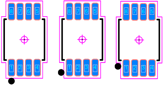
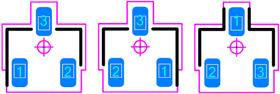
This illustration indicates 3 popular locations for a 0.50 mm dot
on an SOP package. The preferred polarity dot placement is at the end of the
pad which is the furthest distance from the component package body. This makes
the post assembly inspection process easy, as the component package may move up
or down during assembly reflow but the dot will always be visible.
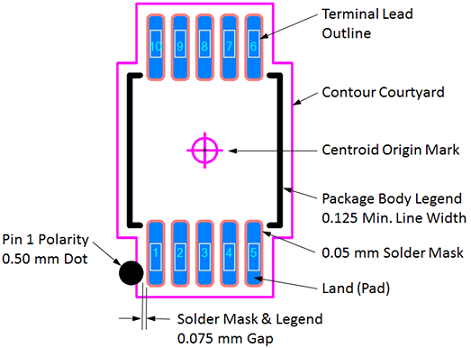
The component body outline legend line width should be a minimum
of 0.12 mm. The Polarity Marking Symbol and component body legend should have a
minimum 0.75 mm gap from the solder mask. The figure below illustrates the
anatomy of a land pattern and feature sizes and spaces.
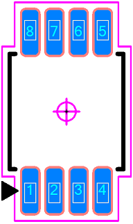
The Triangle Polarity Marking is also popular as it has a unique shape that is easily identified.
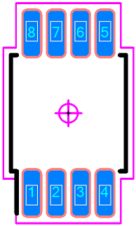
The Line Polarity Marking is also popular because it takes up the least amount of PCB real estate and runs along the entire side of the pad that is visible after assembly.
Here are sample of SOT23 patterns with Polarity Lines:
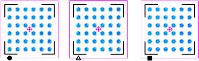
Note: check with your PCB manufacturer to verify if they can meet your dimensional requirements for all land pattern features. Bottom only termination packages – BGA, LGA, CGA, QFN, PQFN, SON,
PSON and DFN
The polarity marking size should match the Terminal Width. The gap
between the body legend and the polarity marker should range from 0.15 mm –
0.25 mm
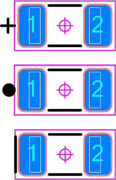
Here is an example of Polarized chip capacitors packages. Normally, the plus + sign is used to indicate a Capacitor, but if you are standardizing on a Dot polarity marker, you may consider the Filled Dot. However, the Line polarity marker takes up less space for high density designs. To obtain the highest level of symmetry in your PCB layouts, all polarity marking shapes, sizes and locations should be documented as your company standard. The Polarity Line can be the same line thickness as the body
legend outlines or thicker, but not thinner.
Assembly
Polarity Marking The Assembly Drawing Polarity Marking can be accomplished by using a chamfered outline in the corner where pin 1 is located: Here is an example of a custom connector Legend and Assembly polarity marking. The black lines are Legend and the Yellow lines are Assembly.
A round filled dot is also an acceptable Assembly Polarity Marker. |
|
 |
|
|
|
|
Post Reply
|
|
| Tweet |
| Forum Jump | Forum Permissions You cannot post new topics in this forum You cannot reply to topics in this forum You cannot delete your posts in this forum You cannot edit your posts in this forum You cannot create polls in this forum You cannot vote in polls in this forum |


 Topic Options