|
|
Dismantling skill of SMT processing |
Post Reply 
|
| Author | |
Cannizzaro 
New User 
Joined: 11 Jul 2018 Status: Offline Points: 2 |
 Post Options Post Options
") Thanks(0) Thanks(0)
 Quote Reply Quote Reply
 Topic: Dismantling skill of SMT processing Topic: Dismantling skill of SMT processingPosted: 12 Jul 2018 at 12:22am |
|
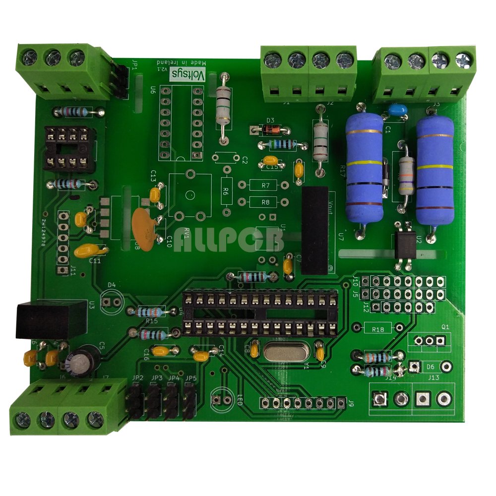
What are the techniques for the dismantling of SMT patches? In general, it is not so easy to remove SMT patches. If you keep practicing regularly, you will be proficient in it. Otherwise, if forced dismantling, it will be easy to destroy SMD components. The mastery of these techniques is of course practiced. Roughly divided into three cases, here ALLPCB would like to share the below points:
1. For components with few pins, such as resistance, capacitance, diode, triode etc., tin on one of the pads on the PCB board, then use the tweezer to hold the component to the mounting position and hold it against the board. The right-hand solders the pins on the tinned pads with a soldering iron. The left-hand tweezers can be loosened and the tin wire is used to weld the remaining feet. It is also very easy to disassemble such components, as long as the two ends of the component are heated simultaneously with a soldering iron, and the components can be removed after the solder is melted.
2. For components with a large number of pins in the SMT processing component, a patch device with a wide pitch is similarly applied. First, tin on one of the pads first, and then use your left hand to solder one pin with a tweezer., then solder the remaining feet with tin wire. The disassembly of such components is generally better with a heat gun, a hand-held hot air gun blows the solder, and the other hand removes the component with a clamp such as a tweezer. 3. For components with a high pin density, the soldering step is similar, that is, soldering pin first, then soldering the remaining legs with tin. The number of pins is relatively large and dense, and pin-to-pad alignment is critical. Usually, the pads are selected on the corners, only a small amount of tin is plated, the components are aligned with the pads with tweezers or hands, the sides of the pins are aligned, the components are pressed on the PCB with a little force, and the solder is soldered with a soldering iron. The corresponding pins of the disk are soldered well.
Finally, it is recommended that the high-pin-density components be disassembled mainly with a heat gun, clamp the components with tweezers, blow all the pins back and forth with a heat gun, and lift the components when they are melted. If the removed component is still needed, then try not to face the center of the component when blowing, and the time should be as short as possible. After removing the components, clean the pads with a soldering iron. |
|
 |
|
|
|
|
Post Reply
|
|
| Tweet |
| Forum Jump | Forum Permissions You cannot post new topics in this forum You cannot reply to topics in this forum You cannot delete your posts in this forum You cannot edit your posts in this forum You cannot create polls in this forum You cannot vote in polls in this forum |


 Topic Options