

|
|
Customizations in calculator should be lockable |
Post Reply 
|
| Author | |
gvellet 
Active User 
Joined: 26 Jun 2021 Status: Offline Points: 46 |
 Post Options Post Options
") Thanks(0) Thanks(0)
 Quote Reply Quote Reply
 Topic: Customizations in calculator should be lockable Topic: Customizations in calculator should be lockablePosted: 14 Apr 2022 at 11:12am |
|
Hi,
When using the calculator, PCB library doc strongly suggests that pin 1 indicator should be added by hand instead of the automatic way. I agree the automatic way is too dumb to be useful, it places the dot right in front of the pad where most likely a via will be placed and obliterate the dot. And also there is no way to move it. But placing of the pin 1 dot by hand or adding a keepout have a big draw back too. All customizations will be wiped out if I change any dimensions and then click calculate. There should be a way to tell the software to preserve all customizations. You might say that an alternative is to transfer the footprint into the footprint designer. But this option has severe limitations, you lose the pin dimensions, the STEP model, the pin outline, and you lose the ability to rebuild footprint for less/nominal/most density level. All for now, GV |
|
 |
|
|
|
|
Tom H
Admin Group 

Joined: 05 Jan 2012 Location: San Diego, CA Status: Offline Points: 5716 |
Post Options
Thanks(0)
Quote Reply
Posted: 14 Apr 2022 at 12:22pm |
|
The most important thing to remember about manually inserting polarity marking is to manually add them last.
However, you have a good point about putting the automatic silkscreen polarity marking to the left of pin 1 rather than at the end of pin 1. We've heard this suggestion before. As a result, by popular demand we're relocating the automatic Pin 1 marking to the left of Pin 1 for all footprints that have a Toe that is larger than the package width. This will not affect any BTC (Bottom Terminal Components) like Grid Array's, DFNs, Pullback Lead PSON & PQFN, etc. Thank you for your feedback. This new feature will be in the next release of V2022.06 pre-release tomorrow or this weekend. We'll let you know. |
|
|
|
|
gvellet
Active User
Joined: 26 Jun 2021 Status: Offline Points: 46 |
Post Options
Thanks(0)
Quote Reply
Posted: 14 Apr 2022 at 3:34pm |
|
Hi Tom,
Having the automatic polarity marker improved is a good thing. Hopefully some control will be given in the drafting tab of the part to offset the marker and to select among the 9 different shapes. Still it would be great, that after a part is released, then we could revise it, change some dimensions while having an option to preserve the keepout and hand placed markers. Since it seems difficult to implement, maybe we can dream of this feature in a future major revision of the software. Best regards, GV |
|
|
|
|
Tom H
Admin Group
Joined: 05 Jan 2012 Location: San Diego, CA Status: Offline Points: 5716 |
Post Options
Thanks(0)
Quote Reply
Posted: 14 Apr 2022 at 4:24pm |
|
All silkscreen "clearance to pad" and "min/max dot size" are defined in Options.
At least we got this far after 6 years of customers asking for this. 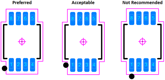 And here are the elements of a Land Pattern:  |
|
|
|
|
carid34
New User 
Joined: 28 Jun 2024 Status: Offline Points: 1 |
Post Options
Thanks(0)
Quote Reply
Posted: 28 Jun 2024 at 5:25am |
|
I understand your concern.
Unfortunately, the current software lacks customization preservation. Manually adding the pin 1 indicator remains the best workaround despite its limitations.
|
|
|
|
|
Tom H
Admin Group
Joined: 05 Jan 2012 Location: San Diego, CA Status: Offline Points: 5716 |
Post Options
Thanks(0)
Quote Reply
Posted: 28 Jun 2024 at 9:09am |
|
Manually added Pin 1 Polarity Markings are saved to FPX file.
There are many different polarity marking shapes to choose from.  |
|
|
|
|
Post Reply
|
|
| Tweet |
| Forum Jump | Forum Permissions You cannot post new topics in this forum You cannot reply to topics in this forum You cannot delete your posts in this forum You cannot edit your posts in this forum You cannot create polls in this forum You cannot vote in polls in this forum |


 Topic Options