

|
|
Additional Footprint Information |
Post Reply 
|
Page 12> |
| Author | |
Vinny_D 
New User 

Joined: 12 Sep 2012 Location: Canada Status: Offline Points: 9 |
 Post Options Post Options
") Thanks(0) Thanks(0)
 Quote Reply Quote Reply
 Topic: Additional Footprint Information Topic: Additional Footprint InformationPosted: 12 Sep 2012 at 1:16pm |
|
Once a footprint is created, the "Footprint" tab should include the following items as well:
- Pad center to center - Silk outline dimensions (x & y) - Courtyard outline dimensions (x & y) Two reasons for this ... this information is available to us in the original LP Wizard tool and secondly, for those of us who are a more visual type of person, having that information easily visible is a quick and handy check. Presently, if you need to look at that information you have to perform multiple, time consuming steps ... it would be really nice if the "Footprint" tab was expanded to have additional information as shown below. Thanks for your consideration, Vince 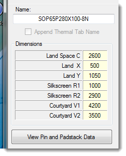 |
|
 |
|

|
|
|
|
|
Jeff.M
Admin Group 

Joined: 16 May 2012 Location: San Diego Status: Offline Points: 501 |
Post Options
Thanks(0)
Quote Reply
Posted: 12 Sep 2012 at 1:37pm |
|
All that information and more can be gotten by Querrying an object.
To querry anything set the Footprint Viewer toolbar button to 'Select' (the arrow) With the mouse in a clear space, right-mouse-button and select the object type to querry (pins, lines, shapes, text or labels). Note this won't work without a valid calculated part. To querry pins, make the Top layer top-selected layer. Select a pin (it highlights) and right-mouse-button select Properties. You can go into all the padstack info by clicking the padstack button in the properties dialog box. To querry shapes or lines make the layer the shape is on the top selected layer. Select the object (it highlights) and right-mouse-button select Properties. I think you'll find this both easier and more detailed than what you get from LPW. |
|
|
|
|
Vinny_D
New User
Joined: 12 Sep 2012 Location: Canada Status: Offline Points: 9 |
Post Options
Thanks(0)
Quote Reply
Posted: 12 Sep 2012 at 1:43pm |
|
Hi Jeff .. yes I am aware of the Query feature, but that takes time and mouse clicks .. I would like to be able to see that information easily and quickly, without having to go through multiple steps to get it ... part of my being a "visual" type of person who likes certain information easily visible and available ... just a personal preference I am used to from using LPW for a number of years ... and the information I am asking for is (I am assuming) readily available and would be easy to add ... just my two (Canadian) cents ...
Thanks, Vince
|
|
|
|
|
Mattylad
Advanced User 

Joined: 02 Jun 2012 Location: Lancashire UK Status: Offline Points: 152 |
Post Options
Thanks(0)
Quote Reply
Posted: 12 Sep 2012 at 2:06pm |
|
Pad centre to centre is a preferred dimension, as it is this that we use to recreate the footprint in our CAD package. If not supplied we have to do some sums :)
|
|
|
|
|
Tom H
Admin Group

Joined: 05 Jan 2012 Location: San Diego, CA Status: Offline Points: 6074 |
Post Options
Thanks(0)
Quote Reply
Posted: 12 Sep 2012 at 2:14pm |
|
The reason why we put the "S" dimension is because for all "Mfr. Recommended Patterns" that is what is provided on the datasheet.
@Vince - I know you're used to LPW, but we're really interested in "why" do you need all the courtyard dimensions and silkscreen dimensions, etc. in one place? We just need to know what you're looking for in that data? BTW: with LPW most silkscreen outlines were closed polygons and with FPE there are no closed polygon silkscreens. However, if your "User Preferences" map the assembly and silkscreen outline to the Maximum component outline then the data you're looking for is handy in the component dimensions. |
|
|
|
|
Vinny_D
New User
Joined: 12 Sep 2012 Location: Canada Status: Offline Points: 9 |
Post Options
Thanks(0)
Quote Reply
Posted: 12 Sep 2012 at 2:21pm |
|
Two reasons Tom ... one is the same as the above reply from "Mattylad" as I have some customers who want me to create the footprint in their CAD package from scratch or by using and editing an existing footprint (don't ask me why - that's what my customer wants and pays me for) ... and second, is that one of the same customers who, as a QC process, re-inputs the information from the spec sheet and uses the information I am asking for as a different means to check my footprint ... it has worked flawlessly in the past using this method ... we have a 99.9% success rate with our footprints ... and we have been using LPW so far ... I would like to try and convince them to move over, but without that data being readily available, I don't know if I can convince my customer ... just saying ...
Vince
|
|
|
|
|
Mattylad
Advanced User
Joined: 02 Jun 2012 Location: Lancashire UK Status: Offline Points: 152 |
Post Options
Thanks(0)
Quote Reply
Posted: 19 Sep 2012 at 12:17pm |
|
I think this is basically the same as http://www.pcblibraries.com/forum/footprint-dims_topic145.html
A request for additional information that can be calculated from the information in the footprint to be displayed. Its not that we do not trust your tool To its that we/users want to double check it and not by having to dig out a calculator to do so. The ability to double check a tools output is of paramount importance if the output is to be used on a run of thousands of boards which could potentially have costly consequences if wrong. |
|
|
|
|
Vinny_D
New User
Joined: 12 Sep 2012 Location: Canada Status: Offline Points: 9 |
Post Options
Thanks(0)
Quote Reply
Posted: 02 Dec 2012 at 11:39am |
|
Tom, any chance we may see an improvement in FE based on the above feedback?
|
|
|
|
|
Tom H
Admin Group
Joined: 05 Jan 2012 Location: San Diego, CA Status: Offline Points: 6074 |
Post Options
Thanks(0)
Quote Reply
Posted: 02 Dec 2012 at 12:45pm |
|
This is one of those issues of advanced technology replacing old technology.
Example of the short term future: We can spend our time adding "Print Feature", "Showing Additional Footprint Dimensions", adding a ton of new features that only some users need. Example of the long term future: 30 million packages available on "Parts on Demand" (POD) website to allow the entire industry to Search, Find, Add-to-Cart and Download every logical part number in the world mapped to 400,000 physical packages. Offer free parts to people who upload parts and charge $1 each for those who do not upload library content. So, in the near future, every part number in the world will already have all the component dimemsions, physical and logical attributes and the user can define their personal preferences to automate custom library creation. Every part will be QC'd and 5-star rated and there will be nothing to QC. We don't want to spend our time creating things that will be obsolete in the near future. This is a distraction from the ultimate goal. In the V2013 program, there will be interactive editing to allow much more flexibility for those who want to be creative. The first new addition to the program will be the "Package Editor" for through-hole connectors and then extended to all non-standard component families. This will allow the user to interactively size, place and name the drill holes and insert a component body outline and save that data to a .pkg file. The program will use your personal preferences to auto-generate the padstacks, drafting outlines and ref des. The second addition will be the mfr. recommended "Footprint Editor" for surface mount connectors and then extended to all non-standard SMT component packages. This will allow the user to automate the process of creating complex pad patterns and QFN's with multiple thermal pads and save the data in a new .FPT (footprint) file. Our goal is to create a PCB library editing program that can automate the process of library construction. And the days of entering component dimensions will be concluded once the "Parts on Demand" (POD) website comes on-line. Our goal is to have every component package in the world in a FPX, PKG or FPT file format available on the internet to search, find, add-to-cart, download, import into the PCB Footprint Expert and allow the user to interactively edit whatever elements they need and save that edited data and auto-generate the PCB library parts that will be 100% compliant to your corporate or customer rules. |
|
|
|
|
Matthew Lamkin
Advanced User
Joined: 02 Oct 2012 Status: Offline Points: 284 |
Post Options
Thanks(0)
Quote Reply
Posted: 03 Dec 2012 at 2:12am |
|
And how will we verify the dimensions of the 30 million packages Tom?
Query each one, get the calculator out and query each item? Surely this cannot be
While we do trust you we need to make sure, to verify what the tool is giving the user to ensure it matches the users requirements.  |
|
|
|
|
Post Reply
|
Page 12> |
| Tweet |
| Forum Jump | Forum Permissions You cannot post new topics in this forum You cannot reply to topics in this forum You cannot delete your posts in this forum You cannot edit your posts in this forum You cannot create polls in this forum You cannot vote in polls in this forum |


 Topic Options
 both easier and more detailed than what you get from LPW