
 |

|
Bourns TBU-CA Series Pad Layout |
Post Reply 
|
| Author | |
Lars P M 
New User 
Joined: 07 Aug 2012 Location: Denmark Status: Offline Points: 3 |
 Post Options Post Options
 Thanks(0) Thanks(0)
 Quote Quote  Reply Reply
 Topic: Bourns TBU-CA Series Pad Layout Topic: Bourns TBU-CA Series Pad LayoutPosted: 04 Sep 2012 at 5:38am |
|
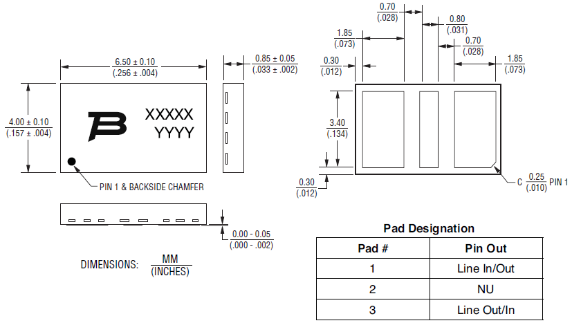
Anybody here having experience with the Bourns TBU-CA High Speed Protectors?
I think the datasheet description of the Pad Layout is a bit unclear. What Component Category should be used to make the layout? Thanks |
|
 |
|

|
|
 |
|
sgdavies 
Advanced User 
Joined: 27 Aug 2012 Location: Germany Status: Offline Points: 140 |
 Post Options Post Options
 Thanks(0) Thanks(0)
 Quote Quote  Reply Reply
 Posted: 04 Sep 2012 at 7:45am Posted: 04 Sep 2012 at 7:45am |
|
Hi Lars,
The datasheet says its a DFN package:- However the 3 pins are arranged different than this tool. so I probably would use the 2 pins DFN option and modify it for 3 pins. or just draw it yourself.. not sure if that helps  The TBU® high-speed protector placed in the system circuit will monitor the current with the MOSFET detection circuit triggering to provide an effective barrier behind which sensitive electronics will not be exposed to large voltages or currents during surge events. The TBU® device is provided in a surface mount DFN package and meets industry standard requirements such as RoHS and Pb Free solder refl ow profi les. |
|
 |
|
Tom H 
Admin Group 

Joined: 05 Jan 2012 Location: San Diego, CA Status: Offline Points: 5985 |
 Post Options Post Options
 Thanks(0) Thanks(0)
 Quote Quote  Reply Reply
 Posted: 04 Sep 2012 at 9:42am Posted: 04 Sep 2012 at 9:42am |
|
This Bourns TBU-CA is a 3-Pin DFN but it's the first one I've ever seen with 3 pins in a row -
 We will have to create a new component family template for this part, but in the meantime you can create the library part using the 2-pin DFN and add the middle pin in your CAD tool library editor. I would make the size of the middle pin the same size 0.05 mm annular ring larger than the lead size. Are there any more of these 3-pin DFN parts out there? We do not like to create component families for unique one-of-a-kind package. This request for a new component family belongs in the "Product Suggestions" Forum - |
|
 |
|
Lars P M 
New User 
Joined: 07 Aug 2012 Location: Denmark Status: Offline Points: 3 |
 Post Options Post Options
 Thanks(0) Thanks(0)
 Quote Quote  Reply Reply
 Posted: 04 Sep 2012 at 11:58pm Posted: 04 Sep 2012 at 11:58pm |
|
Oh, I didn't realize I hit in between all existing foot prints ;-)
Actually Bourns has a series of different TBU components, e.g. 2-pin different pad size http://media.digikey.com/PDF/Data%20Sheets/Bourns%20PDFs/TBU-KE_Series.pdf 4-pin, 2 rows by 2, different size http://www.bourns.com/data/global/pdfs/TBU-DT.pdf 8-pin, 2 rows by 4, different size http://www.bourns.com/data/global/pdfs/TBU-PL.pdf |
|
 |
|
jameshead 
Expert User 
Joined: 20 Mar 2012 Location: Oxfordshire, UK Status: Offline Points: 576 |
 Post Options Post Options
 Thanks(0) Thanks(0)
 Quote Quote  Reply Reply
 Posted: 05 Sep 2012 at 12:23am Posted: 05 Sep 2012 at 12:23am |
|
I've seen a few crystal oscillators and a couple of filters with a similar kind package I think but I can't put my finger on any specific one at the moment.
|
|
 |
|
Tom H 
Admin Group 

Joined: 05 Jan 2012 Location: San Diego, CA Status: Offline Points: 5985 |
 Post Options Post Options
 Thanks(0) Thanks(0)
 Quote Quote  Reply Reply
 Posted: 20 Jul 2013 at 12:11pm Posted: 20 Jul 2013 at 12:11pm |
|
These parts are very simple to create in the new "V2013 Footprint Designer" and then save to FPX to share with others on the "Parts on Demand" (POD) website library vending machine.
They should only be built once by someone and then shared with the entire electronics industry. |
|
 |
|
Post Reply 
|
|
| Tweet |
| Forum Jump | Forum Permissions  You cannot post new topics in this forum You cannot reply to topics in this forum You cannot delete your posts in this forum You cannot edit your posts in this forum You cannot create polls in this forum You cannot vote in polls in this forum |