

|
|
Molded Body part cell |
Post Reply 
|
| Author | |
Nightwish 
Active User 

Joined: 20 Feb 2012 Location: Shanghai China Status: Offline Points: 33 |
 Post Options Post Options
") Thanks(0) Thanks(0)
 Quote Reply Quote Reply
 Topic: Molded Body part cell Topic: Molded Body part cellPosted: 03 Jul 2012 at 6:45pm |
|
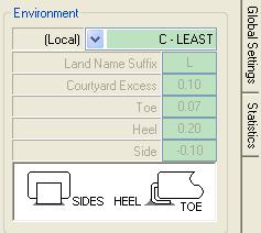
I am using LP Wizard to create a Molded Body inductor and the setting for Side of pad is -0.1mm. The factory guys suggest that pad should be wider than the lead. I am not sure why LP Wizard uses this kind of settings. Please see picture below. I use level C when created the cell.
 Thanks,
Nightwish
|
|
 |
|

|
|
|
|
|
Tom H
Admin Group 

Joined: 05 Jan 2012 Location: San Diego, CA Status: Offline Points: 6074 |
Post Options
Thanks(0)
Quote Reply
Posted: 03 Jul 2012 at 6:53pm |
|
This is the IPC-7351 standard. There is extra "pad width" generated by the Fabrication and Assembly Tolerances in the math. Sop when you use negative values for Side Goal you're only compensating for the other tolerances.
However, the LP Wizard User has full editing control of all the User Settings. Change the Molded Body Side Goal to 0.05 or any value the OEM wants. |
|
|
|
|
Nightwish
Active User
Joined: 20 Feb 2012 Location: Shanghai China Status: Offline Points: 33 |
Post Options
Thanks(0)
Quote Reply
Posted: 03 Jul 2012 at 7:01pm |
|
Hi Tom,
Thanks for your fast reply
I read the IPC7351 but can not find any words talking about this. Can you show me in which Chapter IPC7351 has a definition on this?
Also what is the benefit of this negative setting compared to a larger value? Or if there is other potential risk if we use a negative value during PCBA?
Thanks,
Nightwish
|
|
|
|
|
Tom H
Admin Group
Joined: 05 Jan 2012 Location: San Diego, CA Status: Offline Points: 6074 |
Post Options
Thanks(0)
Quote Reply
Posted: 03 Jul 2012 at 7:07pm |
|
IPC-7351B Page 19 Table 3-13 "Inward Flat Ribbon L-Leads" (top of page)(Molded Inductors, Diodes & Polarized Capacitors)
Notice the Toe, Heel and Side Goals for "Nominal" environment and Side = -0.05 |
|
|
|
|
Nightwish
Active User
Joined: 20 Feb 2012 Location: Shanghai China Status: Offline Points: 33 |
Post Options
Thanks(0)
Quote Reply
Posted: 03 Jul 2012 at 7:14pm |
|
Great!
I have IPC-7351A on hand and I found that table. I will try to explain this to the factory guys and hope there is no big issue during PCA. |
|
|
|
|
Tom H
Admin Group
Joined: 05 Jan 2012 Location: San Diego, CA Status: Offline Points: 6074 |
Post Options
Thanks(0)
Quote Reply
Posted: 04 Jul 2012 at 10:08am |
|
IPC says there does not need to be a "Side Goal" for Molded Body packages because it doesn't do anything to improve the assembly attachment. i.e.: a side goal on Molded Body Inward L-Bend lead does nothing for the overall solder joint strength.
However, the Toe and Heel Goals are very robust for this component family and this is where the solder joint strength is. Also, not having a side goal aligns the package straight on the pads. If you add a side goal, the Molded Body part can drift during reflow and come out of the oven at an angle. Think about it, the Inward L-Bend component lead is just a piece of formed sheet metal and what good would a side goal perform on a thin piece of sheet metal?  |
|
|
|
|
Nightwish
Active User
Joined: 20 Feb 2012 Location: Shanghai China Status: Offline Points: 33 |
Post Options
Thanks(0)
Quote Reply
Posted: 05 Jul 2012 at 5:08am |
|
I confirmed this with our DFME and we made agreement that the cell is ok. Good news is the factory accept our library
|
|
|
|
|
Post Reply
|
|
| Tweet |
| Forum Jump | Forum Permissions You cannot post new topics in this forum You cannot reply to topics in this forum You cannot delete your posts in this forum You cannot edit your posts in this forum You cannot create polls in this forum You cannot vote in polls in this forum |


 Topic Options