

|
|
Collapsing vs: Non-Collapsing BGA Balls |
Post Reply 
|
| Author | |
lsday 
Active User 
Joined: 15 Dec 2014 Status: Offline Points: 24 |
 Post Options Post Options
") Thanks(0) Thanks(0)
 Quote Reply Quote Reply
 Topic: Collapsing vs: Non-Collapsing BGA Balls Topic: Collapsing vs: Non-Collapsing BGA BallsPosted: 06 Apr 2016 at 7:37am |
|
How does one know if the BGA (CSP) has collapsing or non-collapsing solder balls?
|
|
 |
|

|
|
|
|
|
Tom H
Admin Group 

Joined: 05 Jan 2012 Location: San Diego, CA Status: Offline Points: 6075 |
Post Options
Thanks(0)
Quote Reply
Posted: 06 Apr 2016 at 7:44am |
|
Non-collapsing BGA's normally are 0.50 mm pitch or less. There are various Chip Scale Packages where the mfr. calls the package a BGA but instead of a Ball there is only a bump. This is also a non-collapsing BGA. All other BGA's are Collapsing Balls.
|
|
|
|
|
lsday
Active User
Joined: 15 Dec 2014 Status: Offline Points: 24 |
Post Options
Thanks(0)
Quote Reply
Posted: 06 Apr 2016 at 9:09am |
|
Thank you for the clarification Tom.
|
|
|
|
|
Tom H
Admin Group
Joined: 05 Jan 2012 Location: San Diego, CA Status: Offline Points: 6075 |
Post Options
Thanks(1)
Quote Reply
Posted: 30 Jun 2016 at 7:21am |
|
This is what a Collapsing BGA Ball looks like -  Here is a non-collapsing BGA ball with a solder mask defined pad. IPC has guidance to avoid this, but it's impossible for pin pitches below 0.65 mm if there are traces on the same layer. 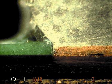 |
|
|
|
|
Eng. Jesus Mora
Advanced User 

Joined: 11 Jul 2013 Status: Offline Points: 56 |
Post Options
Thanks(0)
Quote Reply
Posted: 10 Aug 2018 at 10:12am |
|
Hello Tom,
For fine pitch BGA's using the non-collapsing ball in PCB Library expert program we always have default Solder mask expansion of 0 mils. Do you recommend for all fine-pitch non-collapsing ball to use 0 mils expansion? or what is your recommendation for SM expansion in these cases? Thanks
|
|
|
|
|
Tom H
Admin Group
Joined: 05 Jan 2012 Location: San Diego, CA Status: Offline Points: 6075 |
Post Options
Thanks(0)
Quote Reply
Posted: 10 Aug 2018 at 11:34am |
|
Non-collapsing BGA balls start at 0.50 mm pitch and less.
The pad size is larger because you need to do via-in-pad and you need an annular ring. The solder mask swell = 0 or even -0.05 mm to solder mask define. Even if you can use 2 mil trace/space to escape the second rows, the solder mask must always cover the trace to avoid solder bridging between trace and pad. A 0.50 mm pitch non-collapsing ball size average is 0.25 mm diameter with a pad of 0.33 mm diameter. This leaves a 0.17 mm gap between pads. 0.05 mm trace/space = 0.15 mm but you must consider a 0.025 mm tolerance on the solder mask registration. 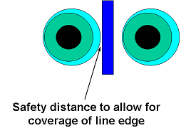 |
|
|
|
|
m.elsayed
Committee 
Joined: 22 Sep 2016 Status: Offline Points: 269 |
Post Options
Thanks(0)
Quote Reply
Posted: 11 May 2026 at 8:29pm |
|
Is the information on collapsing or non collapsing be mentioned in supplier datasheets?
Or does it just depend on the pin pitch value only? Also is the pitch value found in IPC-7352 standard?
|
|
|
|
|
Tom H
Admin Group
Joined: 05 Jan 2012 Location: San Diego, CA Status: Offline Points: 6075 |
Post Options
Thanks(0)
Quote Reply
Posted: 12 May 2026 at 8:01am |
|
The Non-Collapsing BGA calculator is used on fine pitch parts when you can't fanout all the pins in the PCB layout and you're only fanout option is via-in-pad.
Non-Collapsing BGA pads are bigger then collapsing BGA pads to allow an annular ring for the drilling process. Also, if you need to solder mask define the BGA pad to pass drop tests, the solder mask will help with the pad attachment to the prepreg. During drop tests, the ball to pad joint will withstand a drop test, but a non solder mask defined pad could rip away from the prepreg causing the device to malfunction. |
|
|
|
|
Post Reply
|
|
| Tweet |
| Forum Jump | Forum Permissions You cannot post new topics in this forum You cannot reply to topics in this forum You cannot delete your posts in this forum You cannot edit your posts in this forum You cannot create polls in this forum You cannot vote in polls in this forum |


 Topic Options