|
|
Allegro Component Outline/Terminal Issue with Chip |
Post Reply 
|
| Author | |
GrungyRemnant 
Advanced User 
Joined: 17 Oct 2013 Status: Offline Points: 91 |
 Post Options Post Options
") Thanks(0) Thanks(0)
 Quote Reply Quote Reply
 Topic: Allegro Component Outline/Terminal Issue with Chip Topic: Allegro Component Outline/Terminal Issue with ChipPosted: 22 Sep 2016 at 7:03am |
|
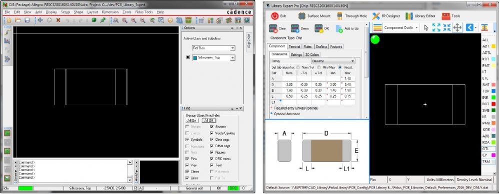
Hi. When importing into Allegro and sending the Component outline, including terminals to
the CAD output there is a problem with Chip parts. I haven't noticed this issue with the other families.
The outline/terminal line is incomplete. Please see the attached image comparing the PCBLEP expected output to the actual Allegro import. Note the missing line. There should actually be 3 separate line paths with 4 segments each, 1 for the outline and 2 for the terminals. Can this please be corrected? This problem is present in version 2016.10 and 2016.11 Regards, Chris
|
|
 |
|

|
|
|
|
|
chrisa_pcb
Moderator Group 

Joined: 29 Jul 2012 Location: San Diego Status: Offline Points: 772 |
Post Options
Thanks(0)
Quote Reply
Posted: 22 Sep 2016 at 3:39pm |
|
i'll take a look at it.
Have you actually moved that terminal outline and ensured the bottom part isn't actually there? It could be a graphical issue on Cadence's part. I find it highly unlikely that the component rectangle itself isn't fully formed.
|
|
|
|
|
GrungyRemnant
Advanced User
Joined: 17 Oct 2013 Status: Offline Points: 91 |
Post Options
Thanks(0)
Quote Reply
Posted: 23 Sep 2016 at 7:45am |
|
Hi Chris. Yes I confirmed it’s not a graphical issue. I looked into it a little more and found the problem. The problem is actually two fold.
The first problem is you are sharing lines at the body start/end vertex. While your script pick points are correct Allegro will merge lines when picking the start/end of a path. Below are the script lines in question, I’ve added the allegro command line feedback as a comment where the problem occurs (“Merged with existing line. Start next line.”) . As soon as the left terminal picks the lines start/end they merge and the line disappears. The remaining 2 vertices are added as a new separate line. The right terminal doesn’t have a problem because it never picks the start/end point. I believe the only way to avoid this would be to have the component body rectangle start/end away from the terminal picks, ie in the middle somewhere. You’ll see the same issue with Oscillator, Corner Concave for example since the pins are at the corners. Having all of that, lol, there is an allegro environment variable that can correct this: addline_nomerge The default value is to have this unset. When unset the problem described above manifests its self. When you set this variable there will be no issue with the line drawings. To set or unset it type the following at the Allegro command line: set addline_nomerge unset addline_nomerge Hope this helps. Chris Script snippet: # Graphics add line setwindow Form.mini FORM mini lock_direction Off FORM mini class PACKAGE GEOMETRY FORM mini subclass DISPLAY_TOP FORM mini line_width 0.001 setwindow pcb pick -1.6 -0.8 pick -1.6 0.8 pick 1.6 0.8 pick 1.6 -0.8 pick -1.6 -0.8 done add line setwindow Form.mini FORM mini lock_direction Off FORM mini class PACKAGE GEOMETRY FORM mini subclass DISPLAY_TOP FORM mini line_width 0.001 setwindow pcb pick -1.1 0.8 pick -1.1 -0.8 pick -1.6 -0.8 #Merged with existing line. Start next line. pick -1.6 0.8 pick -1.1 0.8 done add line setwindow Form.mini FORM mini lock_direction Off FORM mini class PACKAGE GEOMETRY FORM mini subclass DISPLAY_TOP FORM mini line_width 0.001 setwindow pcb pick 1.1 -0.8 pick 1.1 0.8 pick 1.6 0.8 pick 1.6 -0.8 pick 1.1 -0.8 done |
|
|
|
|
chrisa_pcb
Moderator Group
Joined: 29 Jul 2012 Location: San Diego Status: Offline Points: 772 |
Post Options
Thanks(0)
Quote Reply
Posted: 23 Sep 2016 at 10:56am |
|
so I can just use: set addline_nomerge at the start of adding the graphics and: unset addline_nomerge at the end. And everything will be good? :> That's easy enough.
|
|
|
|
|
chrisa_pcb
Moderator Group
Joined: 29 Jul 2012 Location: San Diego Status: Offline Points: 772 |
Post Options
Thanks(0)
Quote Reply
Posted: 23 Sep 2016 at 11:11am |
|
Made the update and confirmed it works, it'll be in the next pre-release. Thanks for narrowing this down. · Allegro/OrCAD PCB – Added a command which turns off the line merge capabilities of Allegro during Graphic placement, and another that turns it back on when done. This should prevent component outlines from accidentally merging with terminal outlines and causing graphical issues. |
|
|
|
|
GrungyRemnant
Advanced User
Joined: 17 Oct 2013 Status: Offline Points: 91 |
Post Options
Thanks(0)
Quote Reply
Posted: 23 Sep 2016 at 11:27am |
|
That would work, unless the user has it set in the first
place then you are changing it on them. :) However I would say
it's a small price to pay to ensure the scripts work.
The other option would be some skill commands at the start and end of the script to get current setting, change it, then restore the user setting at the end. Example script where variable user_addline_nomerge is the users existing setting: skill (user_addline_nomerge = axlGetVariable("addline_nomerge")) (axlSetVariable("addline_nomerge" t)) (exit) # Allegro Script <regular script contents here> #END skill ( unless(user_addline_nomerge axlUnsetVariable("addline_nomerge")) ) (exit) Regards, Chris B |
|
|
|
|
chrisa_pcb
Moderator Group
Joined: 29 Jul 2012 Location: San Diego Status: Offline Points: 772 |
Post Options
Thanks(0)
Quote Reply
Posted: 23 Sep 2016 at 11:52am |
|
skill scripting is only available on full Allegro and not OrCAD PCB, so i'll stick with what we have unless someone complains about the setting. How do you prefer it? In all likelihood, I think it would be more likely that they'll want it set to not merge, but you know far more about Allegro than I do, what is the best setting?
|
|
|
|
|
GrungyRemnant
Advanced User
Joined: 17 Oct 2013 Status: Offline Points: 91 |
Post Options
Thanks(0)
Quote Reply
Posted: 23 Sep 2016 at 12:02pm |
|
Very good.
 I think your solution is completely acceptable as it restores the default value (unset) after running the script. The variables effect on the designer is quite minimal. I would guess most users are probably not even aware of this user preference. |
|
|
|
|
Tom H
Admin Group

Joined: 05 Jan 2012 Location: San Diego, CA Status: Offline Points: 6075 |
Post Options
Thanks(0)
Quote Reply
Posted: 23 Sep 2016 at 5:25pm |
|
A new V2016.11 pre-release is ready to test - www.pcblibraries.com/downloads
|
|
|
|
|
Post Reply
|
|
| Tweet |
| Forum Jump | Forum Permissions You cannot post new topics in this forum You cannot reply to topics in this forum You cannot delete your posts in this forum You cannot edit your posts in this forum You cannot create polls in this forum You cannot vote in polls in this forum |


 Topic Options